Abstract
Entity relationship diagram (ERD) is one of the most widely used technique for data modeling. An ERD developed during the conceptual data modeling phase of the database development process is generally transformed and enhanced through normalization principles during the logical database design phase. This paper suggests inclusion of normalization during ERD development. Application of normalization during ERD development allows for more robust requirement analysis. The paper concludes with a set of guidelines to refine an ERD to include normalization principles.
1.0 Introduction
Entity relationship diagram (ERD) is one of the most widely used technique for data modeling. Data modeling is an essential component of database design and development. It provides a means to analyze business requirements so as to standardize organizational vocabulary, enforce business rules, and ensure adequate data quality. Since data has become a vital corporate resource (Adelman et al., 2005; Dyche, 2000; Liataud & Hammond, 2001), good data models can make a significant contribution to an organization’s future success.
Data modeling is performed during the initial phases of the database development process (also referred as database life cycle) as shown in Figure 1(Mannino, 2006; Rob & Coronel, 2006). During this process, the top two phases are concerned with the information content of the database, while the last two phases are concerned with the implementation of the database on some commercial DBMS.
During the conceptual data modeling phase, data requirements are expressed through an ERD. The conceptual data modeling phase in general is independent of a DBMS. The logical design phase transforms the conceptual data model into a format understandable to DBMS. This phase may also enhance or refine the data model (ERD) of the previous phase to ensure efficient utilization of the database. Since most of the commercial DBMS are based on the relational model, the end product of this phase is relational model design.
One of the ways an ERD is enhanced during the logical design phase is through the process of normalization. Normalization is one of the key tenets in relational model design. It is the process of removing redundancy in a table so that the table is easier to modify (Bala & Martin, 1997; Codd, 1970; Date, 2003; Mannino, 2006; Rob & Coronel, 2006). It usually involves dividing an entity table into two or more tables and defining relationships between the tables. The objective is to isolate data so that additions, deletions, and modifications of an attribute can be made in just one table and then propagated through the rest of the database via the defined relationships.
Normalization utilizes association among attributes within an entity table to accomplish its objective. Since an ERD also utilizes association among attributes as a basis to identify entity type structure, it is possible to apply normalization principles during the conceptual data modeling phase. Performing normalization during ERD development can improve the conceptual model, and speed its implementation. This paper outlines the application of normalization principles to ERD development during the conceptual modeling phase. There are various standards for ERD. In this paper, the Crow’s Foot notation is utilized.
The ERD has received many extensions and variations, which are generally termed as Enhanced Entity Relationship (EER) model (Lenzerini & Santucci, 1983; Lenzerini & Nobili, 1990; Thalheim, 1998; Balaban & Shoval, 1999; Balaban & Shoval, 2002). In the last few years, the Unified Modeling Language (UML) emerged and became the defacto industry standard for many aspects of object modeling (Bock & Ryan, 1993; Booch, 1994; Fowler, 1997; Booch, Rumbaugh & Jacobson, 1999). The EER model is an integral part of UML as all constructs of EER schemas are included, except for weak entity types, to represent the static part of object modeling. However, ERD continues to be popular for conceptual data modeling.
2.0 Application of Normalization to ERD
Data modeling is an iterative process. Generally a preliminary data model is constructed which is then refined many times. There are many guidelines (rules) for refining an ERD. Some of these rules are as follows (Mannino, 2006):
- Transform attributes into entity types. This transformation involves the addition of an entity type and a 1-M (one-to-many) relationship.
- Split compound attributes into smaller attributes. A compound attribute contains multiple kinds of data.
- Expand entity types into two entity types and a relationship. This transformation can be useful to record a finer level of detail about an entity.
- Transform a weak entity type into a strong entity type. This transformation is most useful for associative entity types.
- Add historical details to a data model. Historical details may be necessary for legal as well as strategic reporting requirements. This transformation can be applied to attributes and relationships.
- Add generalization hierarchies by transforming entity types into generalization hierarchy.
Application of normalization principles toward ERD development enhances these guidelines. To understand this application (i) representation of dependency concepts in an ERD is outlined, followed by (ii) representation of normal forms toward the development of entity type structure. Guidelines for identification of various dependencies is avoided in the paper so as to focus more on their application. Only the first four normal forms and the Boyce-Codd normal forms are considered.
2.1 Representation of Dependencies
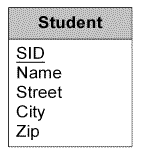
Functional dependency in an entity type occurs if one observes the association among the entity identifier and other attributes as reflected in an entity instance. Each entity instance represents a set of values taken by the non entity identifier attributes for each primary key (entity identifier) value. So, in a way an entity instance structure also reflects an application of the functional dependency concept. For example, the Student entity type of Figure 2 can represent the functional dependency SID ?Name, Street, City, Zip.
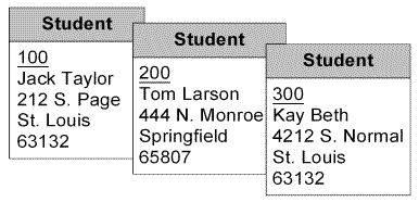
Each entity instance will now represent the functional dependency among the entity attributes as shown in Figure 3.
During requirement analysis, some entity types may be identified through functional dependencies, while others may be determined through database relationships. For example, the statement, “A faculty teaches many offerings but an offering is taught by one faculty” defines entity type Faculty and Offerings. Another important consideration is to distinguish when one attribute alone is the entity identifier versus a composite entity identifier. A composite entity identifier is an entity identifier with more than one attribute. A functional dependency in which the determinant contains more than one attribute usually represents a many-to-many relationship, which is more addressed through higher normal forms. The notion of having a composite entity identifier is not very common, and often times is a matter of expediency, rather than good entity structure or design.
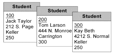
Transitive dependency in an entity type occurs if non entity identifier attributes have dependency among themselves. For example, consider the modified Student entity type as shown in Figure 4.
In this entity type, suppose there is a functional dependency BuildingName ? Fee. Existence of BuildingName ? Fee dependency implies that the value assigned to the Fee attribute is fixed for distinct BuildingName attribute values. In other words, the Fee attribute values are not specific to the SID value of a student, but rather the BuildingName value. The entity instance of transitive dependency is shown in Figure 5.
Multi-valued dependency equivalency in ERD occurs when attributes within an entity instance have more than one value. This is a situation when some attributes within an entity instance have maximum cardinality of N (more than 1). When an attribute has multiple values in an entity instance, it can be setup either as a composite key identifier of the entity type, or split into a weak entity type. For example, consider the following entity type Student Details as shown in Figure 6.
The Student Details entity type has a composite entity identifier consisting of three attributes – SID, MajorMinor, and Activity. The composition of entity identifier is due to the fact that a student has multiple MajorMinor values along with being involved in multiple activities. However, a student has only one value for Name, Street, City, Zip attributes based on the functional dependency SID, MajorMinor, Activity ? Name, Street, City, Zip. The multi-valued dependency affects the key structure. So, in the Student Details entity type, there can be an MVD SID ?? MajorMinor, Activity. This means that a SID value is associated with multiple values of MajorMinor and Activity attributes, and together they determine other attributes. The entity instance of Student Details entity type is shown Figure 7.
2.2 Normalized ERD
Now we utilize the representation of dependency concepts in ERD toward their use in the application of normal forms. Each normal form rule and its application is outlined.
First Normal Form (1NF)
The first normal form rule is that there should be no nesting or repeating groups in a table. Now an entity type that contains only one value for an attribute in an entity instance ensures the application of first normal form for the entity type. So in a way any entity type with an entity identifier is by default in first normal form. For example, the entity type Student in Figure 2 is in first normal form.
Second Normal Form (2NF)
The second normal form rule is that the key attributes determine all non-key attributes. A violation of second normal form occurs when there is a composite key, and part of the key determines some non-key attributes. The second normal form deals with the situation when the entity identifier contains two or more attributes, and the non-key attribute depends on part of the entity identifier. For example, consider the modified entity type Student as shown in Figure 8. The entity type has a composite entity identifier of SID and City attributes.
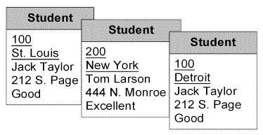
An entity instance of this entity type is shown in Figure 9. Now, if there is a functional dependency City ? Status, then the entity type structure will violate the second normal form.
To resolve the violation of the second normal form a separate entity type City with one-to-many relationship is created as shown in Figure 10. The relationship cardinalities can be further modified to reflect organizational working. In general, the second normal form violation can be avoided by ensuring that there is only one attribute as an entity identifier.
Third Normal Form (3NF)
The third normal form rule is that the non-key attributes should be independent. This normal form is violated when there exists a dependency among non-key attributes in the form of a transitive dependency. For example consider the entity type Student as shown in Figure 4. In this entity type, there is a functional dependency BuildingName ? Fee that violates the third normal form.
Transitive dependency is resolved by moving the dependency attributes to a new entity type with one-to-many relationship. In the new entity type the determinant of the dependency becomes the entity identifier. The resolution of the third normal form is shown in Figure 11. The relationship cardinalities can be further modified to reflect organizational working.
Boyce-Codd Normal Form (BCNF)
The Boyce-Codd normal form (BCNF) extends the third normal form. The Boyce-Codd normal form rule is that every determinant is a candidate key. Even though Boyce-Codd normal form and third normal form generally produce the same result, Boyce-Codd normal form is a stronger definition than third normal form. Every table in Boyce-Codd normal form is by definition in third normal form. Boyce-Codd normal form considers two special cases not covered by third normal form:
- Part of a composite entity identifier determines part of its attribute, and
- a non entity identifier attribute determines part of an entity identifier attribute.
These situations are only possible if there is a composite entity identifier, and dependencies exist from a non-entity identifier attribute to part of the entity identifier. For example, consider the entity type StudentConcentration as shown in Figure 12. The entity type is in third normal form, but since there is a dependency FacultyName ? MajorMinor, it is not in Boyce-Codd normal form.
To ensure that StudentConcentration entity type stays in Boyce-Codd normal form, another entity type Faculty with one-to-many relationship is constructed as shown in Figure 13. The relationship cardinalities can be further modified to reflect organizational working.
Fourth Normal Form (4NF)
Fourth normal form rule is that there should not be more than one multi-valued dependency in a table. For example, consider the Student Details entity type shown in Figure 6. Now, during requirements analysis if it is found that the MajorMinor values of a student are independent of the Activity performed by the student, then the entity type structure will violate the fourth normal form. To resolve the violation of the fourth normal form separate weak entity types with identifying relationships are created as shown in Figure 14. The StudentFocus and StudentActivity entity types are weak entity types. The relationship cardinalities can be further modified to reflect organizational working. It is now presumed that the Student entity type has the functional dependency SID ? Name, Street, City, Zip.
3.0 Conclusions
Instead of applying normalization principles during the relational design portion of logical database design phase, it is better to apply them during the conceptual modeling phase. Due to the similarity in the notion of an entity type and a relation, normalization concepts when explained or applied to an ERD may generate a richer model. Also, such an application enables a better representation of user working requirements. This application now results in the specification of additional guidelines for refining an ERD. These guidelines can be stated as follows:
- There should be only one dependency in each entity type where the determinant is the entity identifier.
- There should not be any additional dependency among the non entity identifier attributes. Any such additional dependency should be represented by a new entity type with one-to-many relationship.
- If there is a composite entity identifier of three or more attributes it should be ensured that there is only one multi-valued dependency among them.
Study of dependencies among attributes during requirement analysis assist in entity type identifications and cardinality specifications. Since an ERD represents a relational model schema, a normalization ERD improves the modeling effort thereby facilitating a better fit with organizational working.
4.0 References
- Adelman, S., Moss, Larissa and Abai, Majid (2005) Data Strategy, Addison-Wesley, Readings, MA.
- Bala, Mohan and Martin, Kipp (1997) “A Mathematical Programming Approach to Data Base Normalization,” Informs Journal of Computing, Vol. 9, No.1, pp. 1-14.
- Balaban, M. and Shoval, P. (1999). Enhancing the ER model with integrity methods. Journal of Database Management, 10(4),14-23.
- Balaban, M. and Shoval, P. (2002). Enforcing Cardinality Constraints in ER Model with Integrity Methods. In Keng Siau (Eds) Advanced Topics in Database Research, Volume 1, 1-16.
- Bock, D. and Ryan, T. (1993). Accuracy in modeling with extended entity relationship and object oriented data models. Journal of Database Management, 4(4), 30-39.
- Booch, G. (1994). Object-Oriented Analysis and Design with Applications (second edition).
- Reading, MA: Addison-Wesley.
- Booch, G., Rumbaugh, J. and Jacobson, I. (1999). The Unified Modeling Language User
- Guide. Reading, MA: Addison-Wesley.
- Chen P. P. (1976). The entity-relationship model: toward a unified view of data. ACM
- Transactions on Database Systems, 1 (1), 9-36.
- Codd, E. F. (1970) “A Relational Model of Data for Large Shared Data Banks,” Communications of the ACM, Vol. 13, No. 6, pp. 377-387.
- Date, Chris (2003) Introduction to Database Systems, 8th edition, Addison-Wesley, Readings, MA.
- Dyche, Jill (2000) e-Data, Addison-Wesley, Readings, MA.
- Fowler, M. (1997). UML Distilled. Reading, MA: Addison-Wesley.
- Lenzerini, M. and Nobili, P. (1990. On the satisfiability of dependency constraints in entity-
- relationship schemata. Information Systems, 15 (4),45 3-461.
- Lenzerini, M. and Santucci, G. (1983). Cardinality constraints in the entity-relationship model. In Davis, Jejodia, Ng, and Yeh. (Eds.), Entity-Relationship Approach
- Liautaud, B. and Hammond, M (2001) e-Business Intelligence, McGraw-Hill, NJ.
- Mannino, M. V. (2006) Database Design, Application Development, and Administration, Third Edition, McGraw-Hill, NJ.
- Rob, Peter and Coronel, Carlos (2006) Database Systems Design Implementation & Management, Course Technology, Boston, MA.
- Thalheim, B. (1998). Fundamentals of Entity-Relationship Modeling. New York: Springer-Verlag.


