 This is the first part of a three-part series, describing the process of converting a relatively abstract Essential Data Model into a practical Logical Database Design. This part consists of:
An introduction to Essential and Logical models, along with the requirements for systems both to deal with technological constraints, and to address the real specific needs for each potential system/data customer.
–
–
–
–
–
The first two steps in the process are addressed in Part One:
- Step 1 – Perform default database design to create a “first-cut” Logical Model.
- Step 2 – Address issues of super-types and sub-types.
Part Two of this series will address Step 3:
- Step 3 – Deal with computed columns.
Part Three will address Steps 4 and 5, the final steps:
- Step 4 – Deal with parameters
- Step 5 – De-normalize, as necessary
Introduction
In the world of systems development, back in 1989, John Zachman recognized 6 perspectives taken by different players in the system development process [i]. In the years since, the names have changed a bit [ii], but the roles are essentially the same:
- Executive perspective – an overview
- Business owner’s perspective – the players, each in their own language
- Essential perspective – a view of the fundamental, underlying structure of the business
- Designer’s perspective – concerned with a particular technology for data management
- Builder’s perspective – the people doing the work of creating a new system
- Implementation perspective – as seen by the ultimate end user of the system
From the beginning, Mr. Zachman emphasized that these did not simply represent varying levels of detail. To be sure, each was typically in more detail than the previous one, but the views were still fundamentally different. The history of our industry—nay, its drama—is derived from misunderstandings across the rows. For a designer to start designing a database, without understanding what the business owner’s requirements are,leads to very unhappy business owners; not to mention unhappy customers of the company.
For the designer not to understand the subtleties of the essential model can also lead to grief.
This article is intended to clarify the translation required between the essential view and a relational database designer’s view.
More About the Perspectives
To capture the Business Owner’s View is to capture vocabulary. The best “semantic model” is probably simply a comprehensive Glossary with terms and definitions. It is important to recognize in it, however, that each definition is probably “owned” by a particular department, and explicit translations must also be captured. The definition of Marketing’s “customer” probably includes prospects. Sales’ “customer” is someone who has bought something within a specified period. Accounting’s “customer” is someone who owes us money (or, better yet, has paid us).
Note that the assignment here is to capture the language (“semantics”) of the organization as comprehensively as possible, including definitions that recognize different points of view.
The Essential View must capture the semantics of the organization, but it must be a more comprehensive, integrated view, capturing underlying concepts that go across different organizational units. This takes advantage of patterns describing concepts common to most or all organizations. For example, the troublesome term “customer” is converted to the person and organization who plays that role, with the ability to distinguish between those who are looking to buy from us, those who have already bought from us, and those who have paid for their purchases.
The point is that much of the language of a business in the Business Owners’ Views describes not just “things of significance,” but also the roles played by those things.
Some enterprise-level patterns that may be chosen are described in your author’s Enterprise Model Patterns: Describing the World. [iii] [1] This book takes several points of view as well, chief among them are different levels of abstraction. At the first level, it provides a generic view of any commercial enterprise or government organization:
- People and Organizations – The company, customers, employees, vendors, etc.
- Geographic Locations – Geographic areas and points, including countries, states, postal areas, sales areas, and basic surveyed lots.
- Physical Assets – All buildings, physical products, equipment, etc.
- Activities and events – What does the organization do, and why?
- Time – Naturally.
There are of course more complex patterns as well, shown as a second level of abstraction. These cover such things as site management, contracts, marketing, etc., and the actual model of a real company will be more complex still. Some sample real industry models are shown in Abstraction Level 3 in the book.
Note that if the underlying system architecture is based on these basic categories of concepts, it will be much simpler than if it is not. Specifically, the further the extent to which this architecture is followed will make the results more flexible and robust:
- Much of the language of the business may now be rendered as instances of data rather than as the structure of the model.
- Nearly all attributes are treated as being multi-valued. This means that there are one or more separate entity classes dedicated to capturing attributes / parameters / characteristics. The attributes of each of these is “Code” (or “Abbreviation”), “Name,” and “Description.”
- In effect, the essential model is a super-set of the users’ views.
This is a very different view of the world from the Implementation View of the ultimate end user. Where the essential model tended to look at everything as examples of general principles, the end user is looking for an environment that is very concrete. A user interface must reflect the very particular circumstances of a particular transaction. The behavior of the system is an extension of the user’s behavior. Ideally, the user has participated in the modeling sessions and conceded that the general principles applied, but those abstractions have little to do with today’s problems being addressed.
It is the Designer, then, and the Builder, who have to bring those perspectives together. In particular, the Designer creates the specifications for whatever system will be built. These specifications, then, will provide instructions for the Builder (programmer, dba, etc.) who will then construct the final system. Among other things, both the programming environment and the physical hardware introduce constraints that get in the way of implementing the beauty of the essential model. This means that the Designer must understand and take into account the environment where the new system will be implemented. This includes:
- Number of users
- Response time required for each
- Number of various kinds of transactions per minute/hour/day.
- Physical user interface facilities available
- Database Management System and programming language constraints.
- Personal restrictions on the interface
- Etc.
Thus, the database and application design must:
- Be true to the essential model
- Accommodate technical constraints
- Make user views readily available
On to Design . . .
Conversion of a pretty essential model into a practical database design involves five steps:
Step 1: Perform default database design.
Step 2: Resolve sub-types.
Step 3: Deal with computed columns.
Step 4: Deal with parameters.
Step 5: De-normalize, as necessary.
Step 1: Perform Default Database Design
Most CASE tools provide the ability to convert a Conceptual (“essential”) model into a Logical (relational) model. Specifically:
- Each entity class becomes a table.
- Each attribute becomes a
- Each primary identifier becomes a primary key. (Each component of the identifier is a reference to a column in the table.)
- Each role on the “many” end of the relationship becomes a foreign key, composed of pointers to the columns on the other table’s primary key.
- If a relationship from entity type A to entity type B was part of a unique identifier, then the columns in table A that are the foreign key implementation of that relationship become part of the primary key for Table A.
Figure 1 shows an essential entity / relationship diagram. It consists of three entity types:
- Contract – an agreement between two or more Persons, whereupon one agrees to supply the others with instances of one or more Product Types or Activity Types, in return for a specified remuneration.
- Line Item – a component of a Contract which specifies the Product Type to be delivered, including “Price”, “Quantity”, and “Value”.
- Product Type – the definition of a particular kind of physical asset being sold. This exists before any are specified in a Contract / Line Item.
The entities are linked by two relationships that describe their use:
- Each Contract may be composed of one or more Line Items, each of which must be to buy a single Product Type.
- Each Product Type may be bought via one or more Line Items, each of which must be part of one and only one Contract.
Attributes are shown for each entity type, including the data type for each.
Unique identifiers are shown for one attribute of each entity type (indicated by the #), plus the relationship “each Line Item must be part of one and only one Contract (indicated by the vertical line across the relationship).
In each case, attributes are annotated thus:
# Attribute is part of a unique identifier
* Attribute must have a value (mandatory)
o Attribute may be left blank (optional)
In addition, any mandatory “to one” relationship that is also part of an entity type’s unique identifier is identified thus by a short line perpendicular to the line, near the identified entity type.
For example, in Figure 1, Product Type is identified by the attribute “Product ID”, and Contract is identified by the attribute “Contract Number”. Line Item, on the other hand, is identified by the combination of the attribute “Line Number”, and the relationship; each Line Item must be part of one and only one Contract.
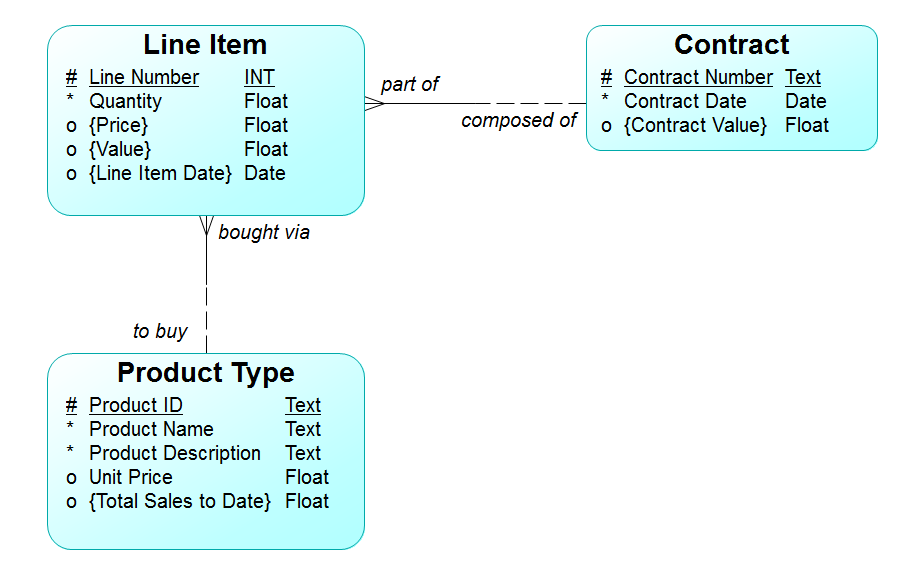
Figure 1: An Entity/Relationship Diagram
Figure 2 shows the result of a generated default design, using the IDEF1 notation:
- Entity Types have been converted to Table Definitions.
- Attributes have become Columns:
- Some columns are labeled <pi> as primary keys
- (Contract) Contract Number <pi>
- (Product Type) Product ID <pi>
- (Line Item) Line Number <pi>
- (Line Item) Contract number <pi, fi1>
- Relationships have become Foreign Keys:
- The lines are converted to IDEF1 relationship notation, keeping relationship names. Initially, all relationship lines are dashed (e.g., Line Item / Product Type) Here, the crows’ foot has been replaced by the solid circle, to mean “may be one or more.” The line without the circle means “must be one and only one.”
(Note that in IDEF1X, the cardinality and optionality are combined into one symbol. The solid circle means—altogether— “may be one or more,” and no symbol means—altogether— “must be one and only one.”)
- Each relationship is implemented by the addition of a column to the “child” table (the one at the “many” end) that is equivalent to the primary key column in the “parent” table.
Columns added to Line Item :
- Contract Number <fi1> (Links to Contract).
- Product ID <fi2> (Links to Product Type)
(Note that the sequence of columns in the foreign key must be exactly the same as the sequence of keys in the primary key.)
- If the relationship in the Essential Model had been part of the entity type’s unique identifier, the implementation of this in IDEF1X is as what is called an identifying relationship. The relationship line, which otherwise would have been dashed becomes solid. The table involved is now called a dependent table, and its square corners then become rounded.
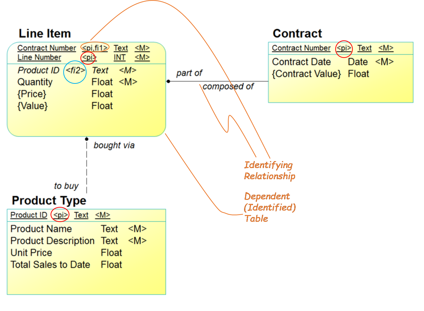
Figure 2: The Default Conversion
An example of this in Figure 2 is the relationship “Each Line Item must be part of one and only one Contract.” In the IDEF1X translation, the column “Contract Number” has been added to Line Item as a foreign key. Because the relationship in the Essential Model was part of the Line Item entity type’s unique identifier, in IDEF1X, the relationship is a solid line, rather than a dashed one. Also, the IDEF1X Line Item “box” has rounded corners, rather than square ones, meaning that the table is now “dependent” on another table.
Step 2: Resolve Sub-types
Some tools, when they convert an essential model to a logical model, maintain the super-type / sub-type structures—either explicitly, or as a collection of “one-to-one” relationships. Eventually, however, to create a relational database design, it is necessary to deal with these “inheritance” structures (as the object-oriented community calls them).
There are no sub-types and super-types in a relational database. By definition, this consists solely of two dimensional tables. At the very least, before the Data Definitions Language (DDL) is created, these issues must be addressed.
There are at least three possible approaches for the conversion:
- Define one table that encompasses the super-type and all of its sub-types.
- All attributes from all sub-types become columns in this table.
- Create a different table for each sub-type.
- Attributes from each sub-type are collected as columns in a separate table.
- Each table also contains columns representing the attributes of all super-types.
- Combinations: some sub-types become separate tables, while others are collapsed into one table that is for the super-type.
Figure 3 shows a sample conceptual model of Party:
This shows two levels of sub-types. Primary, of course is Person and Organization. Organization in turn, is divided into four additional sub-types.
Party has attributes “Identifier Party” and “Name Party”. These will, of course be inherited by all sub-types.
Person has additional attributes “Surname”, “Given Name”, and “Birthdate”. None of these will be inherited by any other entity types.
Organization has the additional attributes “Description Organization”, “Name Organization” and “Purpose”. These will not be inherited by Person, but they will be inherited by the sub-types of Organization.
In addition to the Party and Organization attributes, Legal Value has the attribute “US Tax ID”, and Organization has the attribute “Number Organization” (commonly known as “Organization Number”).
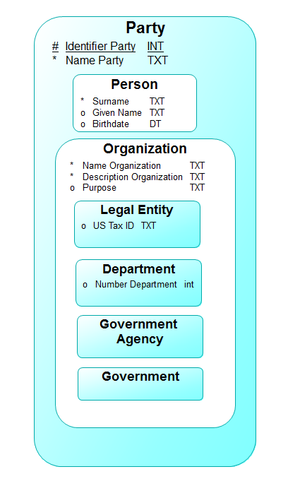
Figure 3: A Sample Essential Model
One Table for All
The first approach involves creating a single table to encompass attributes from both the super-type and all of its sub-types. This has two implications:
- One cannot meaningfully enforce “mandatory” constraints on these columns.
- This requires adding a column, “… Type” (e.g., “Party Type”) to distinguish between instances that are in each of the sub-types.
- Some columns will only take values from instances that are of the specified “… Type”.
An example is shown in Figure 4. Here, the Party entity type as a single table, Party. (By convention, some tools make table names plural, as opposed to the singlular entity type names. For purposes of this exposition, though, we’ve kept the table names singular.) Here, you have:
- Party columns
- Person columns
- Organization columns
- Department columns
- Legal Entity columns
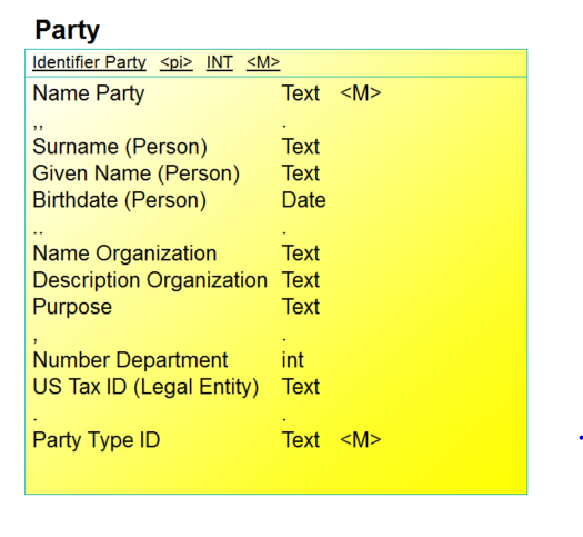
Figure 4: One Table
You also have a new column, “Party Type ID”. For each row of the Party table, this designates it as either describing a “Person”, “Legal Entity”, “Department”, “Government Agency”, or “Government”.
One Table per Entity Type
A second way to convert the essential model to a database design is to convert each sub-type into its own table. Each of these will then include columns from the attributes of that entity type, plus columns for attributes from all inherited super-types. For our party example, this is shown in Figure 5. (Note that the local attributes for each table may now be mandatory.)
Here you see:
- Every table inherits from Party:
- Identifier Party
- Name Party
- Person inherits those, and adds these columns without inheritance:
- Surname
- Given Name
- Birthdate
- Some inherits from Organization:
- Name Organization
- Description Organization
- Purpose
- Legal Entity inherits Party and Organization attributes, and adds the following column, without further inheritance
- US Tax ID
- Department inherits Party and Organization attributes, and adds the following column, without further inheritance
- Number Department.
- Government only inherits Party and Organization
- Government Agency only inherits Party and Organization
Party and Organization do not get converted.
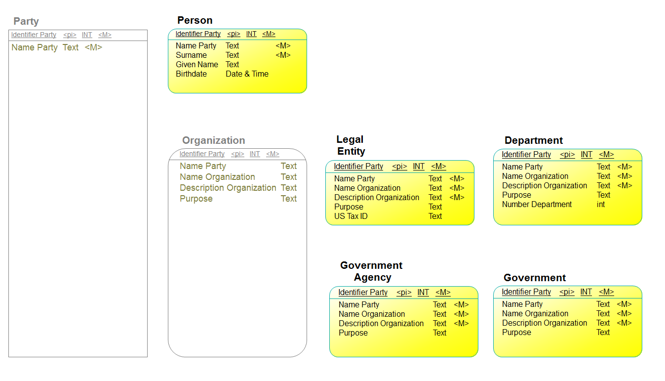
Figure 5: One Table Per Entity Type
Other Combinations
It is in fact, possible to make many other combinations. One example would do the following:
- A Separate table for Person.
- A Separate table for Legal Entity
- A Separate table for all other Organizations
This is shown in Figure 6.
This means that Organization now has an attribute from department, “Number Department”, plus an attribute for distinguishing kinds of organizations, “Organization Type”. Thus, if an instance has an “Organization Type” of “Department”, it may have a value for the attribute “Number Department”.
Instances of Legal Entity won’t show up in Organization, but rather in the table for legal entity itself.
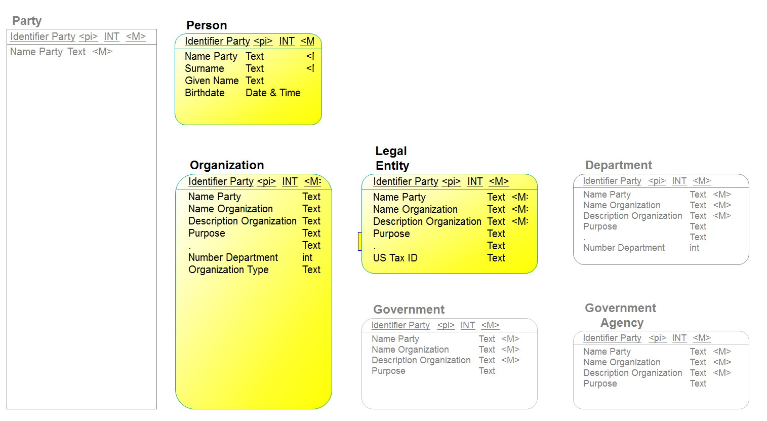
Figure 6: Another Version
Criteria
Note that, while the essential model was based on the essential structure of the party concept, the final database design depends on several other things:
- How many people will want access to each kind of Party.
- How frequently will they be using it.
- What sort of queries will be made?
On to Part Two . . .
Part Two of this series will address Step Three:
- Step 3: Deal with computed columns.
With the final steps, Steps 3 and 4, addressed in Part Three:
- Step 4 : Deal with parameters
- Step 5 : De-normalize, as necessary
References
[i] John Zachman. 1987. “A framework for information systems architecture”, IBM Systems Journal, Vol. 26, No. 3. (IBM Publication G321-5298)
[ii] John Zachman. 2008. “John Zachman’s Concise Definition Of The Zachman Framework™” https://www.zachman.com/about-the-zachman-framework
[iii] David C. Hay. 2011. Enterprise Model Patterns: Describing the World. (Bradley Beach, NJ: Technics Publications).
